
I have played with a bit of Arduino, however decided that i wanted to move more into robotics. This entailed learning about motors, servos, and other bits and pieces. I figured a good way to learn the basics was to purchase a kit, and i wanted it to be a semi decent kit, not just a cheap crappy one that i could not extend later on.
For this reason, i ended up deciding on the RedBot Kit, which had a nice Arduino board with built in motor shield, and things seemed well labeled. It was the nice combination of not to crappy, with not too over priced.
1. Magician Chassis
2. RedBot Board & Sensor Assembly
3. Accelerometer mount
4. Motor connections
5. Arduino IDE
6. Coding
7. Demo Code 1
8. Demo Code 2
9. Demo Code 3
1. Magician Chassis
The kit contains the Magician Chassis which is a good basic chassis that comes with 2 geared motors, good mounting areas, and battery pack. Assembling the Magician Chassi is fairly straight forward, and the instructions are fairly clear if you can view images ( Here are the instructions ). Hint: Ignore the instructions to mount batteries between the layers, its difficult to change them if you do, put them on the top if you can fit them 🙂
I did struggle with getting the motors to fit in the gap and the bolt through the holes to all line up, i found the easiest way was to do the top (or bottom if its up the right way) bolt through with the side clips out, then squish those in and put the bottom bolt in. Careful doing so, the plastic is brittle and may break. It may even pay to sand it down if its too tight (though beware, you don’t want it to be loose!), or use another method to attach the motors.
2. RedBot Board & Sensor Assembly
When it came to adding on the board itself, there were no guides at all, you just had to somehow magically figure it out via trial and error, and a bit of know how. Knowing the basics of Arduino was what got me through, but i thought it best to document it here for anyone else looking. First of all, read the quick start guide, it has a lot of the information at https://learn.sparkfun.com/tutorials/getting-started-with-the-redbot
Start by mountomg the board on the chassis, the following image will help a lot with where and how to fit it.
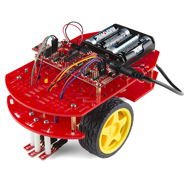
This image is also good to see how the line sensors are mounted on the chassis. When you mount the line sensors make sure the small black dot at the end is facing down, as this is the sensor part, and the pins face the back. Feed the 3 cables from each line sensor up through the body, making sure to stay away from moving parts (wheels etc), and not have them hanging out too much.
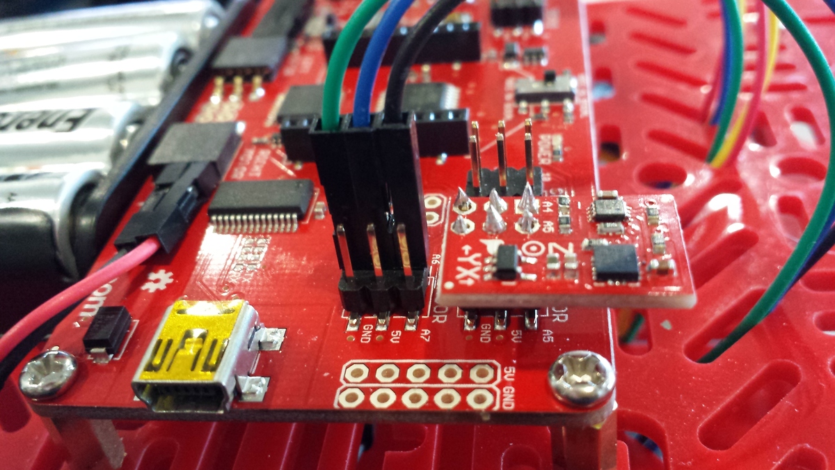
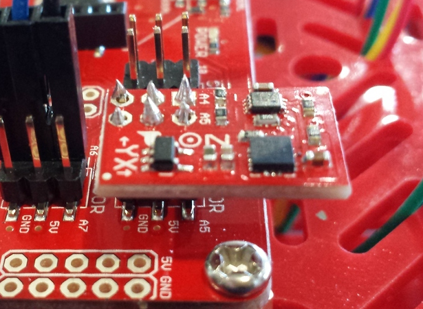
Each sensor has 3 wires, a power, ground, and line for controlling. The Line sensor on the left side goes to the Sensor row labeled A2 , the center one goes to A3, and the right hand one goes to A6. Here are a couple of photos showing mine

I noticed that the sensors are on the BACK not the front of the robot, unsure if this is the correct way, but its how their images show it to be set up. I never actually used mine as yet, if i do it will probably be to stop it falling off a table.
The accelerometer is the only thing needing to be soldered on, though you can always use headers if you wanted on this. The labels on the Accelerometer chip show what pins it goes on and where (A4 and A5) which helps show what way it goes up.
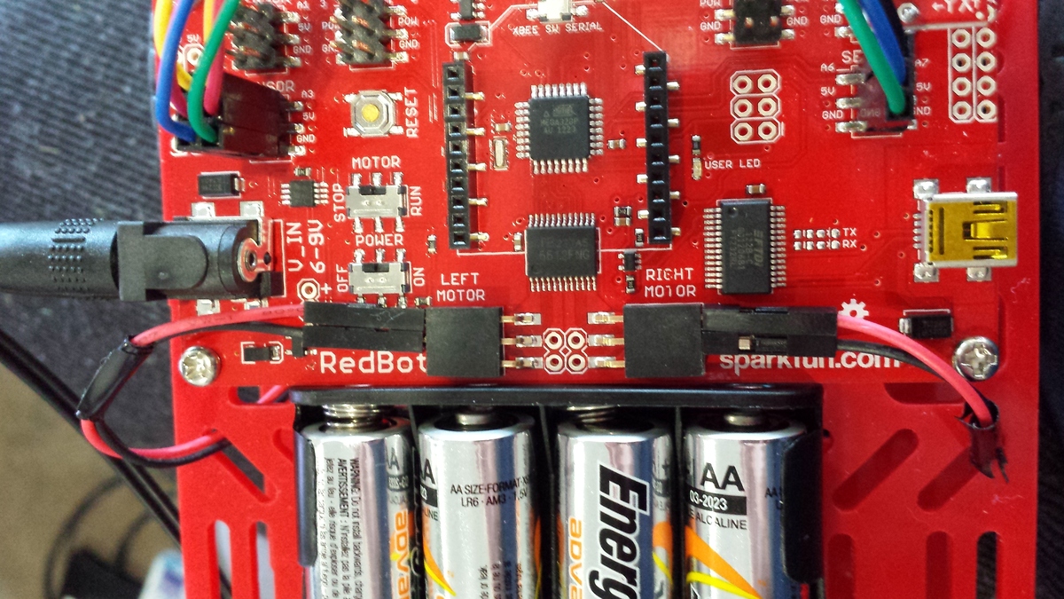
As for the motors, they are fairly self explanatory, 2 wires (red and black) go into the lines for the motors. the only thing to remember is that left goes on the left motor plugs, right on the right motor plugs.
Now you have the whole thing put together, it should work, however you have yet to program it! If you are super new, and unsure about the wiring for sensors, by all means feel free to leave them off (all line sensors and accelerometer are fine and not needed right away)
If you have not already installed the Arduino application, do so now. This allows you to use demo code, and upload or compile your own code for it. Don’t stress if you are unsure about programming, its mostly just a text file with instructions on what the robot needs to do.
The tutorial at the Quickstart is good, but it can be hard for a newbie to figure out installing libraries. First you need the files at http://dlnmh9ip6v2uc.cloudfront.net/datasheets/Robotics/RedBotLibrary.zip . Unzip these, and copy the RedBot folder into the libraries area for Arduino. For Linux this is in ~/sketchbook/libraries/ folder. For windows this is within the My Documents folder in a folder called libraries (if you get stuck see this ).
Now when you open Arduino application, you should be able to look through menus and see examples, and hopefully see RedBot examples. If you can see this, you got it right! If not, may pay to check where you went wrong . If you need help you can ask on the SparkFun Forums at https://forum.sparkfun.com/
Before you think about turning your new robot on, check the switches carefully. You will see there is a Power switch, as well as a Motor on/off switch.

Turn the motor switch to the ‘STOP’ position before you turn it on. This stops the car from driving off whilst you program it. Now you can find a cable to plug into the USB socket on the side (its a fairly generic one, if you don’t have one its easy to buy).
Once plugged in, and powered on, open the Arduino application. In the menus you can click Tools , then Board, and select the board type ‘Arduino mini W/ATMega 328’ . This sets the board type so the code compiles and uploads correctly. Now you are ready to code!
You can use the example code that comes with the RedBot libraries to start with, Its a bit confusing for a beginner to read, but it is a good way to test things are working ok usually. The default code waits for you to tap the accelerometer to start it following a line, so if it does not work right away,give it a tap with your finger.
The RedBot code is explained a little here https://learn.sparkfun.com/tutorials/getting-started-with-the-redbot/arduino-library , how ever i found it a little bit limiting to use, since you do not appear to be able to control the timing of how long you want the motor running for, nor the speed.
I found most tutorials explanation of how they worked was easier to understand which allowed me to program it better to start off with. So here is a basic explanation.
Each motor has 3 pins assigned to it. One is set to either HIGH or LOW, and this one controls motion of the wheel. The next is set to HIGH or LOW and this controls the brake, setting it to LOW takes the brake off and allows the motor to be used. Lastly, the third controls the speed, and this number can be anywhere between 0-255, 255 being full speed.
With that in mind, this is how i did my first program
// setting motor pins as variables. This gives us a name rather than number which is easier to work with.
// Motor 1
int motorafb = 2; // Motor A on pin 2- forward/backwards
int motorab = 4; // Motor A on pin 4 - brake
int motorahs = 5; // Motor A on pin 5 - Speed
int motorbfb = 7; // Motor B on pin 7 - forward/backwards
int motorbb = 8; // Motor B on pin 8 - brake
int motorbhs = 6; // Motor B on pin 6 - Speed

void setup() {

  //Setup Motor A
  pinMode(motorafb, OUTPUT); //Initiates Motor  A pin
  pinMode(motorab, OUTPUT); //Initiates Brake  A pin

  //Setup Motor B
  pinMode(motorbfb, OUTPUT); //Initiates Motor B pin
  pinMode(motorbb, OUTPUT);  //Initiates Brake B pin
  }
void loop(){
// both motors full speed
  //Motor A
  digitalWrite(motorafb, HIGH); //Establishes forward direction of Motor A
  digitalWrite(motorab, LOW);   //Disengage the Brake for Motor A
  analogWrite(motorahs, 255);   //Spins the motor on Motor A at full speed

  //Motor B
  digitalWrite(motorbfb, HIGH);  //Establishes Forward direction of Motor B
  digitalWrite(motorbb, LOW);   //Disengage the Brake for Motor B
  analogWrite(motorbhs, 255);    //Spins the motor on Motor B at half speed

  // Wait 500ms (it will continue to drive during that 500ms)
  delay(500);

  // Turn by turning one motor forward, and one backward at half speed
  digitalWrite(motorafb, LOW);  //Establishes backward direction of Motor A
  digitalWrite(motorab, LOW);   //Disengage the Brake for Motor A
  analogWrite(motorahs, 155);    //Spins the motor on Motor A at half speed

  //Motor B forward @ full speed
  digitalWrite(motorbfb, HIGH); //Establishes forward direction of Motor B
  digitalWrite(motorbb, LOW);   //Disengage the Brake for Motor B
  analogWrite(motorbhs, 255);   //Spins the motor on Motor B at full speed

  // Another delay to let it turn fo 500ms
  delay(500);

 // STOP!
  digitalWrite(motorab, HIGH);  //Engage the Brake for Motor A
  digitalWrite(motorbb, HIGH);  //Engage the Brake for Motor B
  analogWrite(motorahs, 0); // Set speed to 0
  analogWrite(motorbhs, 0);// Set speed to 0
} |
This sketch will loop, essentially making your robot drive in circles nicely. Paste the entire thing into your arduino IDE, make sure the robot is plugged in and switched on, then push the -> or compile/upload button to upload it. Sometimes after plugging in, it takes a few seconds to link too your PC, if it errors, give it a few seconds before trying again. Once uploaded, you can unplug your robot, and switch the motor back on to test.
Test yourself, see if you can make it run in a square using all those above commands!
From here you should be able to play around with it a bit, and then add in sensors to the code.
Here is an example of code with the accel sensor working, so if the bot feels an impact, it reverses and then turns
// We are using the RedBot library for the accelerometer code
#include <RedBot.h>
RedBotAccel xl;

// setting motor pins as variables
int motorafb = 2;
int motorab = 4;
int motorahs = 5;
int motorbfb = 7;
int motorbb = 8;
int motorbhs = 6;

void setup() {

  //Setup Motor Channel A
  pinMode(motorafb, OUTPUT); //Initiates  pin
  pinMode(motorab, OUTPUT); //Initiates Brake Motor Channel A pin

  //Setup Motor Channel B
  pinMode(motorbfb, OUTPUT); //Initiates  pin
  pinMode(motorbb, OUTPUT);  //Initiates Brake Motor Channel A pin

// This is the bit to enable the accelerometer using the RedBot library
  xl.enableBump();
  xl.setBumpThresh(70);
}

void loop(){
// this if statement checks to see if its been bumped, and if it has, it runs the commands inside the {}
 if (xl.checkBump()) {

  digitalWrite(motorab, HIGH);  //Engage the Brake for Motor Channel A
  digitalWrite(motorbb, HIGH);  //Engage the Brake for Motor Channel B
  delay(500);
   //Motor A reversing @ full speed
  digitalWrite(motorafb, LOW);  //Establishes backward direction of Motor Channel A
  digitalWrite(motorab, LOW);   //Disengage the Brake for Motor Channel A
  analogWrite(motorahs, 255);    //Spins the motor on Motor Channel A at half speed

  //Motor B reversing @ full speed
  digitalWrite(motorbfb, LOW); //Establishes forward direction of Motor Channel B
  digitalWrite(motorbb, LOW);   //Disengage the Brake for Motor Channel B
  analogWrite(motorbhs, 255);   //Spins the motor on Motor Channel B at full speed

  delay(1000);

   //Motor A reversing @ half speed
  digitalWrite(motorafb, LOW);  //Establishes backward direction of Motor Channel A
  digitalWrite(motorab, LOW);   //Disengage the Brake for Motor Channel A
  analogWrite(motorahs, 155);    //Spins the motor on Motor Channel A at half speed

  //Motor B forward @ full speed
  digitalWrite(motorbfb, HIGH); //Establishes forward direction of Motor Channel B
  digitalWrite(motorbb, LOW);   //Disengage the Brake for Motor Channel B
  analogWrite(motorbhs, 255);   //Spins the motor on Motor Channel B at full speed

  delay(500);

 } else // This is what happens if nothing has been bumped into
 {
  // both motors full speed
  //Motor A forward @ full speed
  digitalWrite(motorafb, HIGH); //Establishes forward direction of Motor Channel A
  digitalWrite(motorab, LOW);   //Disengage the Brake for Motor Channel A
  analogWrite(motorahs, 255);   //Spins the motor on Motor Channel A at full speed

  //Motor B foward @ full speed
  digitalWrite(motorbfb, HIGH);  //Establishes backward direction of Motor Channel B
  digitalWrite(motorbb, LOW);   //Disengage the Brake for Motor Channel B
  analogWrite(motorbhs, 255);    //Spins the motor on Motor Channel B at half speed

  //delay(1000);
// STOP!

  digitalWrite(motorab, HIGH);  //Engage the Brake for Motor Channel A
  digitalWrite(motorbb, HIGH);  //Engage the Brake for Motor Channel B
  analogWrite(motorahs, 0); // Set speed to 0
  analogWrite(motorbhs, 0);// Set speed to 0

  delay(500);

  //Turn right
  //Motor A forward @ full speed revering
  digitalWrite(motorafb, LOW);  //Establishes backward direction of Motor Channel A
  digitalWrite(motorab, LOW);   //Disengage the Brake for Motor Channel A
  analogWrite(motorahs, 155);    //Spins the motor on Motor Channel A at half speed

  //Motor B forward @ full speed
  digitalWrite(motorbfb, HIGH); //Establishes forward direction of Motor Channel B
  digitalWrite(motorbb, LOW);   //Disengage the Brake for Motor Channel B
  analogWrite(motorbhs, 255);   //Spins the motor on Motor Channel B at full speed

  delay(255);

  digitalWrite(motorab, HIGH);  //Engage the Brake for Motor Channel A
  digitalWrite(motorbb, HIGH);  //Engage the Brake for Motor Channel B

  delay(3000);
 }
} |
This is a demonstration on how a function works, to save you typing the same code all the time. This example is the same as the Demo 1, only it uses a function, thus saving us a lot of copy/paste code later on.
// setting motor pins as variables
// Motor 1
int motorafb = 2; // Motor A - forward/backwards
int motorab = 4; // Motor A - brake
int motorahs = 5; // Motor A - Speed
int motorbfb = 7; // Motor B - forward/backwards
int motorbb = 8; // Motor B - brake
int motorbhs = 6; // Motor B - Speed

void setup() {

//Setup Motor A
pinMode(motorafb, OUTPUT); //Initiates Motor A pin
pinMode(motorab, OUTPUT); //Initiates Brake A pin

//Setup Motor B
pinMode(motorbfb, OUTPUT); //Initiates Motor B pin
pinMode(motorbb, OUTPUT); //Initiates Brake B pin
}

// two functions which turn one motor on, the other off for 'spd' speed, and 'tme' Time

void TurnRight(int spd, int tme){
digitalWrite(motorafb, LOW);
digitalWrite(motorab, LOW);
analogWrite(motorahs, spd);

digitalWrite(motorbfb, 'HIGH');
digitalWrite(motorbb, LOW);
analogWrite(motorbhs, spd);
delay(tme);
}

void TurnLeft(int spd, int tme){
digitalWrite(motorafb, HIGH);
digitalWrite(motorab, LOW);
analogWrite(motorahs, spd);

digitalWrite(motorbfb, LOW);
digitalWrite(motorbb, LOW);
analogWrite(motorbhs, spd);
delay(tme);
}

// Function to go power both motors for 'spd' speed, and 'tme' time
void GoForward(int spd, int tme){
digitalWrite(motorafb, HIGH);
digitalWrite(motorab, LOW);
analogWrite(motorahs, spd);

digitalWrite(motorbfb, HIGH);
digitalWrite(motorbb, LOW);
analogWrite(motorbhs, spd);
delay(tme);
}

// Function to stop for a set amount of time - tme
void Stop(int tme){
digitalWrite(motorab, HIGH);
digitalWrite(motorbb, HIGH);
analogWrite(motorahs, 0);
analogWrite(motorbhs, 0);
delay(tme);
}

void loop(){
// Now we can use them like this

GoForward(255, 500); // So this will go forward full speed (255) fpr 500ms
Stop(1000); // Sits Stopped for 1000ms
TurnRight(255, 1000); // turns Right at full speed for 1000ms
Stop(1000);// Sits Stopped for 1000ms
TurnLeft(255, 1000); // turns Left at full speed for 1000ms
Stop(1000); // Sits Stopped for 1000ms

} |
 Found on facebook – put here to remember


